KIMBO
CREATE BEAUTY FASTER.

Kimbo is a plug-in for Adobe Illustrator that adds 13 new tools to Illustrator's tool palette. These tools permit the creation of artwork that would otherwise be difficult or time-consuming to create.
System Requirements
Adobe Illustrator CC2025, CC2024, CC2023, CC2022, CC2021, CC2020, CC2019, CC2018, CC2017, CC2015, CC2014, CC or Adobe Illustrator CS6.

Installation for Adobe Illustrator CC2023, CC2024 and CC2025 for Macintosh.
- Quit Adobe Illustrator.
- Download and install ZXPInstaller from the link in the demo .zip file.
- Run ZXP Installer
- Drag the appropriate .zxp file for your platform into the ZXPInstaller interface. It will install Kimbo's framework for you.
- Place the Kimbo.aip file in your Plugins folder within Adobe Illustrator
- Launch Adobe Illustrator
- Enter your name and serial number, or use in demo mode for free for 14 days.
- Make a new file.
- Click on the 3 dots on the bottom of your toolbar to see the full list of Tools available. Kimbo's Tools are available in the "Add-On" section at the bottom. Drag desired Tools into your toolbar. You can create customized toolbars by going to Windows -> Toolbars -> New Toolbar...
- If you click on Windows -> Toolbars -> Advanced, Kimbo's tools appear in the original 2 toolbar groupings.
- That’s it!
Installation for Adobe Illustrator CC2023, CC2024 and CC2025 for Windows.
- Unpack kimbo_full.zip to the root of the desired disk.
- Important note: Path should not contain Cyrillic characters, as it will cause errors.
- Quit ALL Adobe applications.
- Drag the appropriate .zxp file for your platform into the ZXPInstaller interface. It will install Kimbo's framework for you.
- Run ZXP Installer
- Drag the appropriate .zxp file for your platform into the ZXPInstaller interface. It will install Kimbo's framework for you.
- Place the Kimbo.aip file in your Plugins folder within Adobe Illustrator
- Launch Adobe Illustrator
- Enter your name and serial number, or use in demo mode for free for 14 days.
- Make a new file.
- Click on the 3 dots on the bottom of your toolbar to see the full list of Tools available. Kimbo's Tools are available in the "Add-On" section at the bottom. Drag desired Tools into your toolbar. You can create customized toolbars by going to Windows -> Toolbars -> New Toolbar...
- If you click on Windows -> Toolbars -> Advanced, Kimbo's tools appear in the original 2 toolbar groupings.
- That’s it!
Installation for Adobe Illustrator CC2021 and CC2022 for Macintosh.
- Quit ALL Adobe applications.
- Download and install ZXPInstaller: aescripts.com/learn/zxp-installer/
- Run ZXP Installer
- Drag the appropriate .zxp file for your platform into the ZXPInstaller interface. It will install Kimbo's framework for you.
- Place the Kimbo.aip file in your Plugins folder within Adobe Illustrator
- Launch Adobe Illustrator
- Enter your name and serial number, or use in demo mode for free for 14 days.
- Make a new file.
- Click on the 3 dots on the bottom of your toolbar to see the full list of Tools available. Kimbo's Tools are available in the "Add-On" section at the bottom. Drag desired Tools into your toolbar. You can create customized toolbars by going to Windows -> Toolbars -> New Toolbar...
- If you click on Windows -> Toolbars -> Advanced, Kimbo's tools appear in the original 2 toolbar groupings.
- That’s it!
Installation for Adobe Illustrator CC2021 and CC2022 for Windows.
- Unpack kimbo_full.zip to the root of the desired disk.
- Important note: Path should not contain Cyrillic characters, as it will cause errors.
- Quit ALL Adobe applications.
- Download and install ZXPInstaller: aescripts.com/learn/zxp-installer/
- Run ZXP Installer
- Drag the appropriate .zxp file for your platform into the ZXPInstaller interface. It will install Kimbo's framework for you.
- Place the Kimbo.aip file in your Plugins folder within Adobe Illustrator
- Launch Adobe Illustrator
- Enter your name and serial number, or use in demo mode for free for 14 days.
- Make a new file.
- Click on the 3 dots on the bottom of your toolbar to see the full list of Tools available. Kimbo's Tools are available in the "Add-On" section at the bottom. Drag desired Tools into your toolbar. You can create customized toolbars by going to Windows -> Toolbars -> New Toolbar...
- If you click on Windows -> Toolbars -> Advanced, Kimbo's tools appear in the original 2 toolbar groupings.
- That’s it!
Installation for Adobe Illustrator CC2020 for Macintosh.
- Quit ALL Adobe applications.
- Download and install ZXPInstaller: zxpinstaller.com
- Run ZXP Installer
- Drag the appropriate .zxp file for your platform into the ZXPInstaller interface. It will install Kimbo's framework for you.
- Place the Kimbo.aip file in your Plugins folder within Adobe Illustrator
- Launch Adobe Illustrator
- Enter your name and serial number, or use in demo mode for free for 14 days.
- Make a new file.
- Click on the 3 dots on the bottom of your toolbar to see the full list of Tools available. Kimbo's Tools are available in the "Add-On" section at the bottom. Drag desired Tools into your toolbar. You can create customized toolbars by going to Windows -> Toolbars -> New Toolbar...
- If you click on Windows -> Toolbars -> Advanced, Kimbo's tools appear in the original 2 toolbar groupings.
- That’s it!
Installation for Adobe Illustrator CC2020 for Windows.
- Unpack kimbo_full.zip to the root of the desired disk.
- Important note: Path should not contain Cyrillic characters, as it will cause errors.
- Quit ALL Adobe applications.
- Download and install ZXPInstaller: zxpinstaller.com
- Run ZXP Installer
- Drag the appropriate .zxp file for your platform into the ZXPInstaller interface. It will install Kimbo's framework for you.
- Place the Kimbo.aip file in your Plugins folder within Adobe Illustrator
- Launch Adobe Illustrator
- Enter your name and serial number, or use in demo mode for free for 14 days.
- Make a new file.
- Click on the 3 dots on the bottom of your toolbar to see the full list of Tools available. Kimbo's Tools are available in the "Add-On" section at the bottom. Drag desired Tools into your toolbar. You can create customized toolbars by going to Windows -> Toolbars -> New Toolbar...
- If you click on Windows -> Toolbars -> Advanced, Kimbo's tools appear in the original 2 toolbar groupings.
- That’s it!
Installation for Adobe Illustrator CC2019, CC2018, CC2017 and CC2015.3 for Macintosh and Windows.
- Quit ALL Adobe applications.
- Install ZXPInstaller
- Run ZXP Installer
- Drag the appropriate .zxp file for your platform into the ZXPInstaller interface. It will install Kimbo's framework for you.
- Place the Kimbo.aip file in your Plugins folder within Adobe Illustrator
- Launch Adobe Illustrator
- Enter your name and serial number, or use in demo mode for free for 14 days.
- That’s it!
Installation for Adobe Illustrator CC2015.2.1 for Macintosh.
- Quit Adobe Illustrator CC2015
- Copy Kimbo.aip to /Applications/Adobe Illustrator CC 2015/Plug-ins.
- Copy all the folders to /Library/Application Support/Adobe/CEP
- Launch Adobe Illustrator CC2015.
- Enter your name and serial number, or use in demo mode for free for 14 days.
- That’s it!
Installation for Adobe Illustrator CC2015 for Macintosh.
- Quit Adobe Illustrator CC2015
- Run “Install Kimbo.command” by right-clicking, selecting “Open” and then hitting the “Open” button.
- Terminal will open.
- Your computer will ask permission for “ExManCmd” to make changes. Enter your password to do this when prompted.
- Terminal will install Kimbo. When you see the text “[Process Completed]”, quit Terminal.
- Launch Adobe Illustrator CC2015.
- Enter your name and serial number, or use in demo mode for free for 14 days.
- That’s it!
Installation for Adobe Illustrator CC2015 for Windows.
- Quit Adobe Illustrator CC2015
- Run “install.bat”
- Launch Adobe Illustrator CC2015.
- Enter your name and serial number, or use in demo mode for free for 14 days.
- That’s it!
Installation for Adobe Illustrator CS6, CC, and CC2014.
- If Adobe Illustrator is open, quit the application.
- Open the Kimbo.zxp file. Adobe Extension Manager will launch. Click "Accept". In the following dialogue, click "Install".
- Kimbo will open a dialogue and prompt you to enter a serial. If you have licensed Kimbo, enter your serial. If not, you are free to try Kimbo free for 14 days, after which time it will no longer function.

General Information
Tools:
Kimbo adds 2 new groups containing 12 tools to Illustrator's list of tools. The new icons appear at the bottom of Illustrator's tool palette.

The 1st group contains 6 path and mesh creation tools whose icons are shown below.

From left to right these are:
- Rose tool
- Wave tool
- Rhombus tool
- Archimedean Spiral tool
- Golden Rectangle tool
- Polar mesh tool
These tools draw new artwork in Illustrator. See the appropriate section for a more detailed description.
The 2nd group contains 6 path manipulation tools whose icons are shown below.

From left to right these are:
- Mirror Tool
- Cut Tool
- Rectangle Cut Tool
- Tile tool
- Rosette tool
- Spike tool
These tools operate on currently selected artwork in Illustrator. See the appropriate section for a more detailed description.
All the path/mesh creation tools plus the mirror and cut tools are actionable.
Effects:
Three of the above tools (Mirror, Cut, and Rectangle Cut) are also implemented as Live Effects in Illustrator.
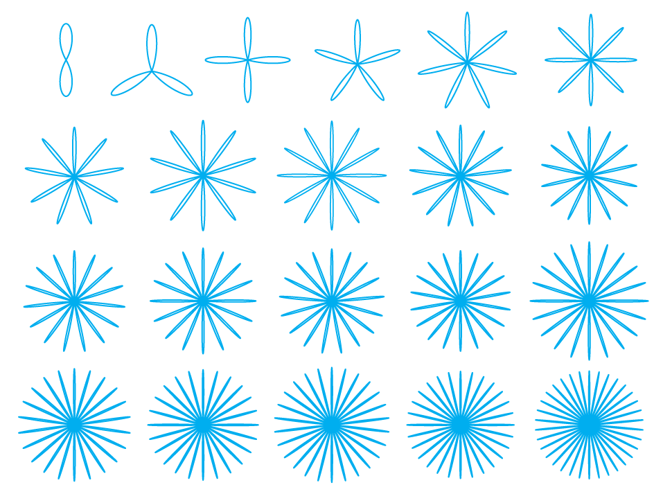
Rose Tool

Create floral shapes with varying radii. You can choose the number of lobes within each shape. Selecting this tool and then clicking and dragging allows the creation of lobed curves in Illustrator. These curves approximate what are termed rhodonea curves, so named because of their similarity to a rose. The up and down arrow keys increase and decrease respectively the number of lobes in the rose. A maximum of 20 lobes are allowed. The right and left arrow keys increase and decrease respectively the thickness of each lobe. Double-clicking the tool or clicking in the artboard brings up a dialog box that allows these settings to be viewed and changed.
Example:
Wave Tool

Create wiggly lines as popularized as of late in trendlist.org. The Wave tool allows you to determine the width, height, and number of waves in each vector shape. Selecting this tool and then clicking and dragging allows the creation of a path that looks like a wave. This path will be a close approximation to a sine wave. The right and left arrow keys increase and decrease respectively the number of waves in the path with a maximum of 20. Holding down the option key draws from the center. Double-clicking the tool or clicking in the artboard brings up a dialog box that allows these settings to be viewed and changed.
Example:

Rhombus Tool

Create rhomboid-shaped paths by entering values or by merely drawing on the canvas. Selecting this tool and then clicking and dragging creates a rhombus. Holding down the option key draws from the centre. Holding down the shift key constrains the scale to be the same in both x and y. Double-clicking the tool or clicking in the artboard brings up a dialog box that allows these settings to be viewed and changed.
Example:

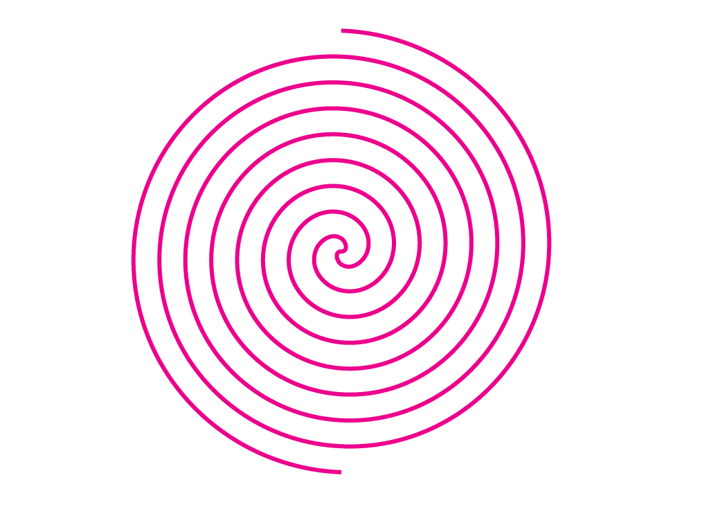
Archimedean Spiral Tool

Selecting this tool and then clicking and dragging allows the creation of a curve called an Archimedean spiral. Illustrator’s native spiral tool creates logarithmic spirals, which approximate most patterns found in nature. The right and left arrow keys increase and decrease respectively the number of turns (maximum: 50, minimum: 0). The R key toggles between an Archimedean spiral and a related “double’ spiral called the Fermat spiral (Fermat being he of “Last Theorem” fame). Holding down the shift key constrains the last point of the spiral to lie either on the x or y-axis. Double-clicking the tool or clicking in the artboard brings up a dialog box that allows these settings to be viewed and changed.
Examples:

This is an Archimedean spiral.
This is a Fermat spiral.
Golden Rectangle Tool
Draw Golden Rectangles on the fly—just select the tool and drag on the canvas to make sacred geometry in real time! Selecting this tool and then clicking and dragging allows the creation of a golden rectangle. Holding down the option key draws from the centre. A golden rectangle is a rectangle whose sides are in the ratio (√5 + 1): 2 (that’s about 1.618). This ratio not only has certain interesting mathematical properties, but was also regarded by the ancient Greeks as being the most aesthetically pleasing of all rectangles. It appears widely in Renaissance art.
Example:

Grid Tool

Instantly create custom grids with predetermined amounts of cells, columns, and rows, as well as absolute sizing. An insane time-saver for web design and print design. Here is the interface for the grid tool:

Within, you can set the number of squares or rectangles in columns and rows, determine their height and width, and force them to be squares if desired. Using the Up and Down keys changes the amount of squares on the Y axis when dragging out a grid on the artboard manually. Using the Left and Right Arrow keys changes the amount of squares along the X axis when dragging out a grid on the artboard manually. Hitting the Option key while creating a grid manually centers it from the point of origin.
Example:
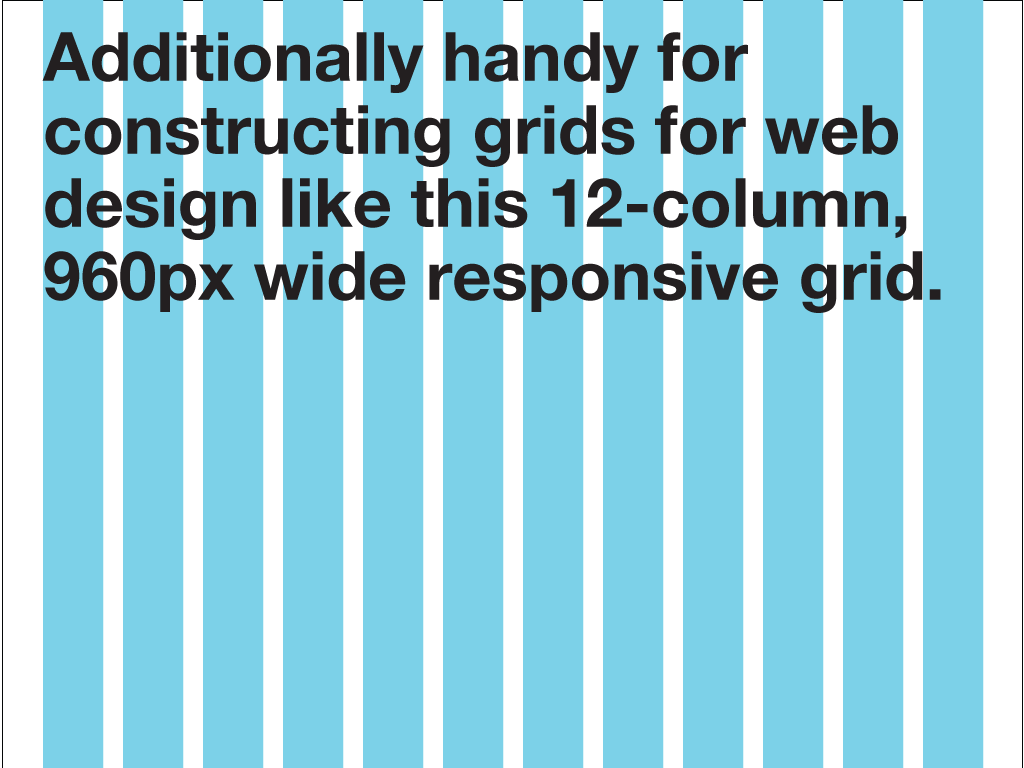
This grid for a standard 12-column 960px wide responsive grid was created by setting two grids - one for the columns and one for the gutters. Much easier than fiddling with guides and the ruler.
Polar Mesh Tool

The Polar Mesh tool creates circular (polar) meshes colored according to an existing fill color or gradient. This tool helps extend the potential of mesh-based coloring in Adobe Illustrator, and allows users to create mesh-based coloring with far more detail.
Selecting this tool and then clicking and dragging creates a gradient mesh in the form of a circle or ring, with the edges of the mesh forming the spokes and concentric radii of the circle.
The up and down arrows change the number of strokes while the left and right arrow keys change the number of radii.
The R and T keys control the size of the inner radius relative to the size of the outer radius. Initially this value is zero which means that the mesh forms a circle: non-zero values will result in a ring.
Holding down the option key draws from the centre.
Holding down the P key toggles between creating a circle and a regular polygon with sides equal to the number of radial lines.
Double-clicking the tool or clicking in the artboard brings up a dialog box that allows these settings to be viewed and changed.
The initial color of the mesh is determined by the current fill color and the color mode setting in the dialog box.
Examples:

Here is a sample mesh created with the default settings and a fill colour of red.

Here the inner radius has been set to 33% so the mesh forms a ring. The polygon flag has been set and the number of radial lines changed to six so that the mesh forms a hexagon. The number of radii have also been increased and the fill style set to a rainbow gradient.

You can select individual points within the polar mesh and tweak colors, just as you can in Illustrator's default gradient mesh.
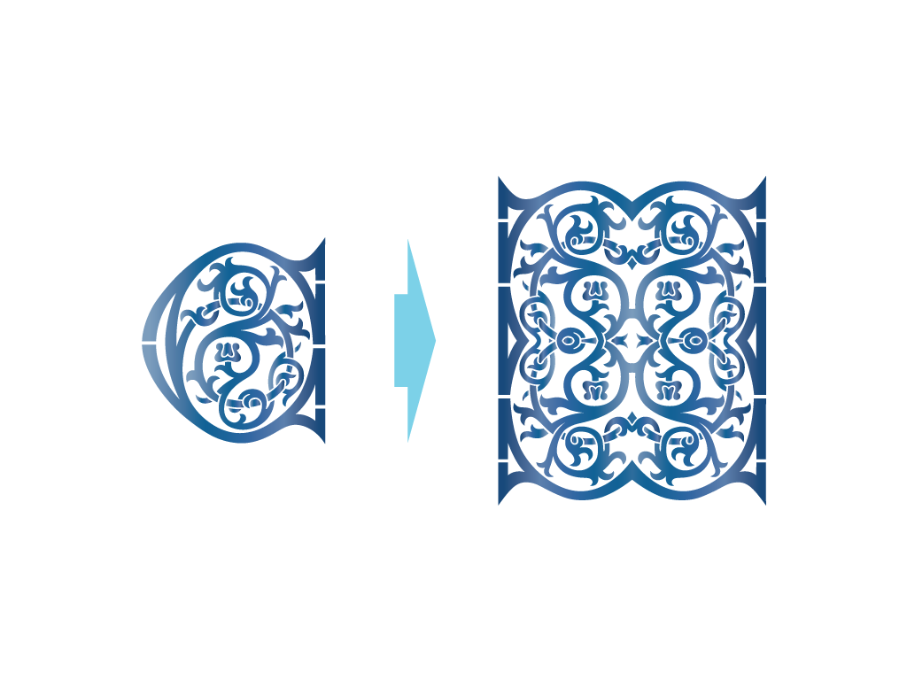
Mirror Tool

The Mirror tool reflects and duplicates art in a specified line, then rejoins it to form a symmetrical construct. Dragging the mouse moves the line which is by default vertical but may be changed, either by the arrow keys to any multiple of 90 degrees or via a dialog box to any desired angle. Fill, stroke, and transparency attributes are maintained. The Mirror tool is essential for designing vector objects which are symmetrical in nature - it is a terrific time-saver for pattern design, illustration, type design and image-making.
Selecting this tool and then clicking and dragging has the following effect on all selected paths and meshes.
- An imaginary line is drawn vertically through the current cursor position.
- All selected artwork is cut by this ‘mirror’ line.
- That part of the artwork that lies to the left of the line is discarded.
- That part that lies to the right is duplicated, reflected in the mirror line, and joined with the original.
A quick example to illustrate the general idea:

Here is a scary and aggressive panther head.

Clicking in the left of the ellipse results in a vertical line (the mirror line) appearing and an arrow pointing in the direction of mirroring.

After releasing the mouse the new art will look like this.
This is a single piece of art, and no masking is involved.
Artwork Affected:
This tool works with multiple paths, compound paths, and gradient meshes. New paths and compound paths will be generated as necessary. However it will not work on text (it is necessary to use the Create Outlines command first) or images. Although it will work on blend art, the results may not be as expected since the spine is affected too. If peculiar results are obtained, the blend should be expanded.
If the tool is applied to a gradient mesh; a path filled with a gradient; a path filled or stroked with a pattern; or a path that is part of a clipping group, then the artwork produced will be slightly different. The reflected artwork is not joined to the original artwork to produce a single piece of art as it would be impossible to produce a gradient for the new art that would appear 'correct'.
Options:
The arrow keys change the direction of the mirror line in the expected way. For example, if the up arrow key is pressed the artwork is mirrored above a horizontal line going through the cursor position.
Double-clicking the tool brings up a dialog box that also allows the direction to be changed.
Holding down the shift key performs an additional mirror using a line rotated 90 degrees clockwise from the original.
Holding down the R key rotates counter-clockwise in increments of 3 degrees; the T key rotates clockwise.
Holding down the control key coerces an open cut as opposed to a closed one. This is only relevant when mirroring artwork filled with a gradient or pattern.
Note: Illustrator's context-sensitive menus may be a problem here: it's best to have the mouse down before pressing the control key.
More Examples:

Compound paths are generated if necessary.

New paths are also generated if necessary.
Holding down the shift key reflects twice.
If the artwork is filled or stroked(!) with a gradient or pattern it is cut, then reflected.

The examples for this section have been pretty lite so far - even if you have really intense vector objects with thousands of points, multiple gradient styes and stroke styles, the Mirror Tool chops and reflects amazingly.
This tool works on multiple selections.

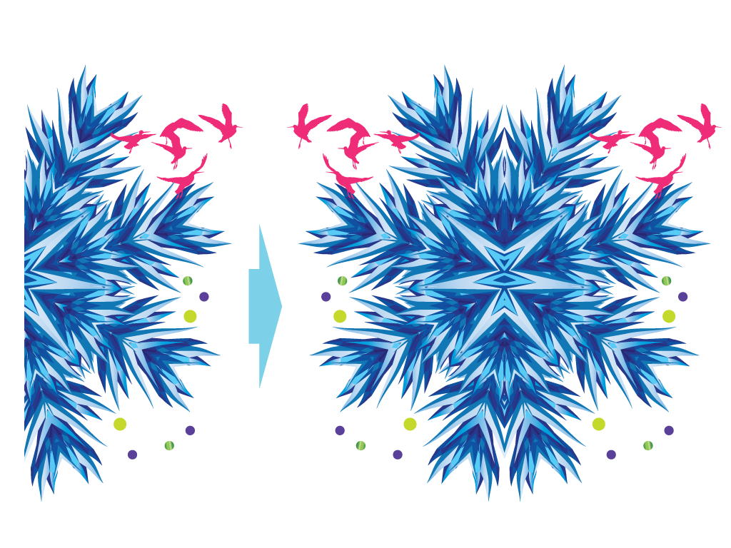
Successive application of this tool (particularly with the shift key held down) can rapidly produce bizarre symmetrical artwork. For example, starting with the crazy mutant space sea urchin, bird silhouettes, and gradated circles above, the construct shown was produced using 2 clicks with the mirror tool (shift key down) with a rotation in between.
Cut Tool
The Cut Tool crops art against a line. Very useful for quickly getting rid of unwanted art.

Selecting this tool and then clicking and dragging has the following effect on the selected artwork:
- An imaginary line (vertical by default) is drawn vertically through the current cursor position.
- All selected artwork is cut by the line.
- That part of the artwork that lies to the left of the line is discarded.

The example above shows the tool applied to an intense amount of vector artwork.

After applying the cut tool the art now looks like this - stray vectors begone! Perfect for cleaning up illustration work with messy edges.
Artwork affected
This tool, like the Mirror tool, works with multiple paths, compound paths, and gradient meshes. New paths and compound paths will be generated as necessary. However it will not work on text (it is necessary to use the Create Outlines command first) or images. Although it will work on blend art, the results may not be as expected since the spine is affected too. If peculiar results are obtained, the blend should be expanded.
By default, the cut is closed if and only if the artwork is closed. This behavior can be changed by use of the modifier keys (see below).
Options
The arrow keys change the direction of the cut line in the expected way. For example if the up arrow key is pressed the artwork is cut above a horizontal line going through the cursor position.
Double-clicking the tool brings up a dialog box that also allows the direction to be changed.
Holding down the shift key performs an additional cut using a line rotated 90 degrees clockwise from the original.
Holding down the R key rotates counter-clockwise in increments of 3 degrees: the T key rotates clockwise.
Holding down the control key coerces an open cut as opposed to a closed one. This is only relevant when cutting filled artwork. Conversely, holding down the command key coerces a closed cut as opposed to an open one (only relevant when cutting unfilled artwork).
Note: Illustrator's context-sensitive menus may be a problem here: it's best to have the mouse down before pressing the control key. A similar situation applies with the command key.
Note 2: Using the control key modifier on closed paths may have the effect of generating compound paths with unclosed members. The Illustrator renderer may in these cases produce single vertical lines. These are artifacts and will not print.
More examples
Holding down the shift key cuts twice:

Holding the control key down coerces an open as opposed to a closed cut (the top example below is the default setting while the bottom is coerced):

This tool works on multiple selections (here shown using an angled cut):

Rectangle Cut Tool
The Rectangle Cut tools crops art against a rectangle . Very useful for quickly getting rid of unwanted art. The Rectangle Cut tool is extremely helpful for cropping imagery for use as the base for pattern design, creating concise artwork for the web, and cleaning up stray paths.
This tool draws the outline of a rectangle on the screen: all selected artwork outside this rectangle is cut against the sides of the rectangle.

Example
In terms of practicality, the Rectangle Cut Tool does wonders at chopping down artwork for pattern-making:

Artwork affected
This tool, like the Mirror tool, works with multiple paths, compound paths, and gradient meshes. New paths and compound paths will be generated as necessary. However it will not work on text (it is necessary to use the Create Outlines command first) or images. Although it will work on blend art, the results may not be as expected since the spine is affected too. If peculiar results are obtained, the blend should be expanded.
By default, the cut is closed if and only if the artwork is closed. This behavior can be changed by the modifier keys (see below).
Options
Holding down the shift key coerces the rectangle to a square.
Holding down the option key draws the rectangle from the centre.
Holding down the control key forces an open cut as opposed to a closed one. This is only relevant when cutting filled artwork. Conversely, holding down the command key coerces a closed cut as opposed to an open one (only relevant when cutting unfilled artwork).
Illustrator's context-sensitive menus may be a problem here: it's best to have the mouse down before pressing the control key. A similar situation applies with the command key.
Using the control key modifier on closed paths may have the effect of generating compound paths with unclosed members. The Illustrator renderer may in these cases produce single vertical lines. These are artifacts only and will not print.
Tile Tool

The Tile tool allows the creation of repeating patterned art in any of the 17 so-called wallpaper groups / lattice symmetries. Simply select some art and then click and drag in the vicinity of the art to produce tiled patterns, which may be based on a rectangle, square, parallelogram, triangle, rhombus, or hexagon depending on the symmetry group. Play with the up/down arrow keys to cycle through the symmetry groups. The possibilities are boundless - you just need to play with this tool to discover its capabilities.
Operation
The Tile tool works as follows:
- Select some art
- Click and drag in the vicinity of the selected art
- Release the mouse
The document gets filled with art according to the following rules:
- The mouse-down position and the current mouse position together define a base tile. The nature of this tile depends on the current symmetry group, but it is typically a rectangle or a triangle.
- The selected art is clipped to the boundaries of this base tile in a manner analogous to the Cut tool. This art will be termed the pattern motif.
- This motif is now replicated to form a lattice unit, which may be a rectangle, hexagon, rhombus, square, or a parallelogram. From 1-12 base tiles make up a lattice unit (depending on the symmetry group). Each replication of the motif is accompanied by a rotation, reflection, or glide reflection (reflection + translation) of the base tile from which it was derived.
- The lattice unit is replicated and translated as much as necessary to fill the document, and is then cut to the edges of the document.
Example:
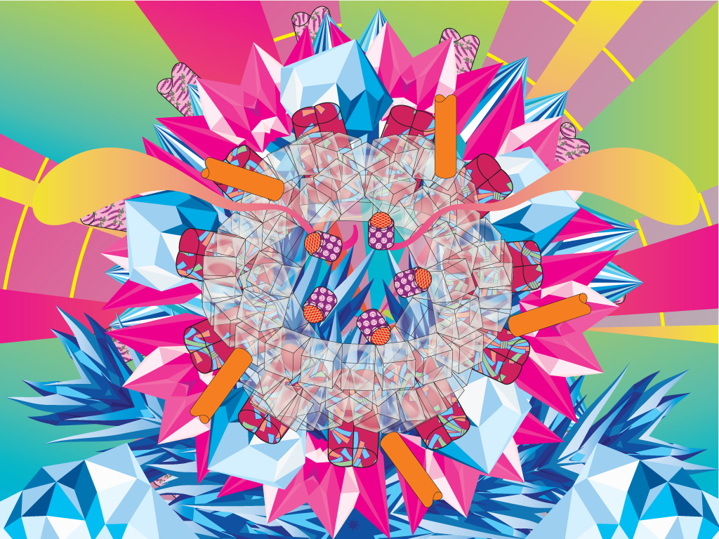
- The artwork is a "crystal" and the symmetry group is called p3 (number 13: this can be changed if necessary by using the dialog box brought up by double-clicking the tool).
- Select the crystal; then select the tile tool and click at a position near the lower-left corner of the crystal.
- Drag the mouse towards the centre of the crystal. Some outlined artwork will appear.
- The base tile is shown as the blue double-edged rhombus (a rhombus with internal angles of 60 and 120 degrees being the base tile for the p3 symmetry group). The other 2 blue-outlined pieces of art are part of the preview: they show the lattice unit in artwork mode.
- The pattern motif is determined by the intersection of the base tile with the selected art:
- This motif is replicated twice: each replication being accompanied by a rotation of 120 degrees around the start point (these happening to be the rules for the p3 symmetry group we are using). This now constitutes the lattice unit which (again for p3) is a hexagon:
- The lattice unit is now replicated and used to cover the document (scaled down and cut):

The resulting artwork is heavily grouped: to examine the contents of a lattice unit it is necessary to ungroup it.
Changing the symmetry group
The symmetry group (1-17) may be changed in one of 2 ways:
- Use the up/down arrow keys while the mouse is down to increase or decrease respectively the number of the symmetry group.
- Use the menu in the dialog box (obtained by double-clicking the tile tool).
The top half of the dialog box has the following appearance:

The symmetry group menu changes the group, while the box below gives detailed information about the group. Specifically, the shape of the base tile and lattice unit, how many base tiles make up a lattice unit, and (if you're interested!) the International Crystallographic Notation for the symmetry group.
Defining the base tile
The size and position of the base tile (which can be a square, rectangle, triangle, or parallelogram depending on the symmetry group) are determined by the user in terms of the mouse-down position and the current mouse position.
However it should be noted that the base tile itself is often constrained in shape. While some symmetry groups can use any rectangle as a base tile, others may require a square or a triangle with specific internal angles (e.g. the p4m symmetry group has a base tile consisting of triangles whose angles are 45, 45, and 90 degrees). In such cases the proportions of the base tile must be maintained, so it may be necessary to experiment with dragging the mouse in each direction to get the desired effect.
There are 2 symmetry groups (1 and 2) which have base tiles of a parallelogram and a triangle (any triangle) respectively. In these cases the 2 mouse positions (start and current) are insufficient to define a base tile, so the left and right arrow keys are used to introduce a skew factor. There is a lower limit to the size of the base tile: otherwise it is too easy to create excessive amounts of art with this tool. In any case, a warning is issued when the mouse is released if the size of the generated art is deemed to be excessive.
Tile/Pattern mode
There is a radio group in the dialog box called tile type. The mode by default is tile, but it can be set to pattern (In addition to the radio group buttons, this mode can be toggled by tapping the T and P keys respectively while the mouse is down).
Pattern mode differs from tile mode in this respect: the selected art itself is the pattern motif (i.e. it is not clipped to the base tile: step 2 in the generating process being omitted).
To illustrate this idea, consider a selection consisting of an ellipse filled with the rainbow gradient. Using the p6 symmetry group (number 16) we can generate the lattice unit (top), while in pattern mode the result is very different (bottom). Since there is no clipping the resultant artwork is much larger and there is an overlapping effect:
It is easy to generate large, perhaps even unnecessary quantities of art with this tool, especially in Pattern mode.
Some tips to prevent this from happening:
- Have a limited amount of art pieces in the current selection
- Make these pieces of art small
- Drag a longer distance vs. a shorter one
- Use a small-numbered symmetry group (fewer base tiles needed to make up a lattice unit)
Kimbo will issue a warning if too much pattern art is selected when this tool is invoked (or when pattern mode is selected).
Clip Mode
When artwork is clipped in the tile tool, either by cutting the current selection to the base tile or by clipping at the edge of the document, the same rules are followed as for the Cut and Rectangle Cut tools. Whether it is an open cut or closed cut depends upon whether the artwork is filled or not: behavior that can be overridden using the control or command key.
A further option in the dialog box is the Closed Cut checkbox.
This applies to symmetry groups where there are mirror reflections included in the process whereby a lattice unit is built up from the base tile (this applies to any symmetry group whose crystallographic name contains an 'm', e.g. p6m). If this option is set the artwork is cut before mirroring (resulting in more stroke lines).
To demonstrate the effect, here is an ellipse (symmetry group p3 – single lattice only) with the clip preview on left and the resulting closed cut (top right) and without closed cut (bottom right):

Other options
There is a radio group in the dialog box whose buttons control the extent of the lattice unit replication. The default is document (the whole view), but it can also be set to single lattice (no replication), or the artboard or page (in the centre). Holding down the escape key while releasing the mouse button acts as a 'Cancel' key.
Gallery
The simplest symmetry of all is obtained by laying out a motif in a rectangular grid. This can be achieved by using symmetry group 1 (p1), and setting the skew of the parallelogram to 0 with the left/right arrow keys.
Example:
Applying these settings to this little stressball gives you a fairly straightforward tiled pattern:

If you change the settings to p2, you get:

If you change the settings to p3, it results in:

If you change the settings to p4, you get this:

You can repeat ad nauseum, and the results are more and more interesting with increased complexity.
Another example
Starting with p3 symmetry in pattern mode, then applying pm symmetry in tile mode, you get this:

Or the p12 symmetry type:

Let's kick it up a notch to p17 symmetry type!:

BAM!
These tilings give just a taste of what can be achieved with this tool.
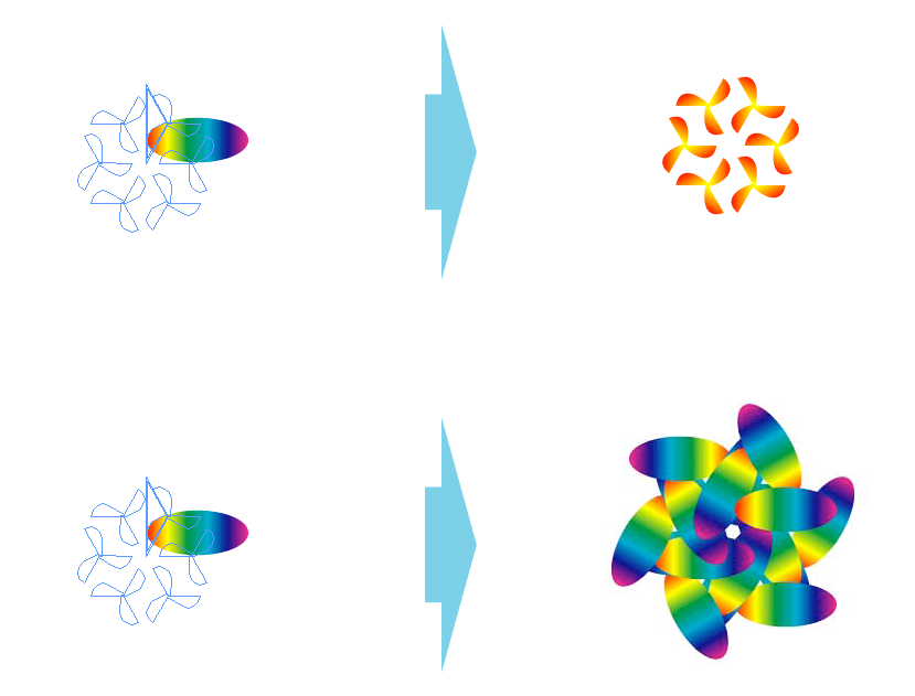
Rosette Tool

The Rosette tool operates in a similar way to the tile tool but creates patterns with circular (and, optionally) mirror symmetry. Perfect for creating abstract ornament, compositions based on repetition, and general experimentation.
This tool allows objects with rotational symmetry to be created using the currently selected path or paths as a motif.
The tool is used by selecting some artwork, invoking the rosette tool, clicking in the centre of the rotation and dragging the artwork. 2 lines are drawn from the centre of symmetry: they can be thought of as a cone whose interior angle is equal to 360 divided by the number of lobes. These lines define that part of the selected art that is to be used in the symmetry pattern.
As an example, consider the selected art shown below on the left. Here is a rosette with both mirroring and cutting turned off with 7 lobes. Clicking and dragging over the original diamond shape results in the art shown on the right.

Double-clicking the rosette tool icon brings up a dialog box that can be used to change settings. Here is the Rosette Tool applied with both cutting and mirroring and 20 lobes applied:

Number of lobes
The number of lobes can be changed from 1 to 50 (the default is 8) either by pressing the up/down keys or by changing the slider/text field in the dialog box.
When the shift key is held down while dragging the cone is constrained to angles that are a multiple of the number of lobes, thus resulting in a pattern that aligns correctly with the y axis.
Mirror
When mirror mode is on (default) the selected artwork is mirrored in a line that lies in the middle of the lobe. Hitting the M key toggles mirror mode on and off: it can also be changed using the appropriate checkbox in the dialog box. The difference is shown below: when mirror is off the pattern on the left is produced; when it's on, the image on the right is seen.
Technically, when mirror mode is on the resultant pattern shows dihedral symmetry: when it is off it is termed cyclic symmetry. Here is a rosette using only mirroring and no clipping with 10 lobes:

Clip
Here is a 10-lobed rosette with no mirroring and clipping applied:

Here is a 10-lobed rosette with both mirroring and clipping applied:

When clip is set (default) the artwork is clipped along the lines defined by the cone. Toggling this off, either by hitting the C key or by deselecting the checkbox in the dialog box, results in no clipping. The difference can be illustrated as follows (top = no clipping applied / bottom = clipping applied:

In general, the Rosette Tool is excellent for making ornament, pattern, bases for pattern swatches, and tons of gorgeous abstract form!
Spike tool

The Spike tool is an interactive tool that, as its name suggests, can be used to add spikes to selected paths and gradient meshes. With the Spike tool selected, the mouse is clicked on one side of the selected path; then dragged across the path to the other side and released.
Holding down the shift key coerces the spike to be vertical or horizontal.
Holding down the up or down key respectively sharpens or blunts the spike with respect to the drag length. After repeated invocation of the down key the spike tool becomes equivalent to adding an anchor point.
Double-clicking the tool or clicking in the artboard brings up a dialog box that allows these settings to be viewed and changed.
Example:
With an ellipse selected, the mouse was clicked at A and dragged to B, resulting in an extra anchor point added to the ellipse.

Repeated application of the tool to a gradient mesh (left) or a polar mesh (right) results in effects that appear both vaguely topographic and vaguely rhizomatic.

Effects
The Mirror, Cut, and Rectangle Cut tools are also implemented as Live Effects. They can be accessed from Effects->Kimbo and operate in the expected way.
Restrictions
- The Mirror, Cut, Rectangle Cut, and Tile tools will not work on text art, raster art, or graph art. Results with gradient blends may be counterintuitive (see relevant chapter).
- The Mirror, Cut, Rectangle Cut, and Tile tools will not recognize artwork that consists of a single point only.
References
References on tiles and patterns
- Tilings and Patterns by Grunbaum, B., and Shephard, G.C. This book is widely regarded as the definitive work on the subject. It is now out of print but you may find a suitable copy at the library.
- Symmetries of Islamic Geometrical Patterns by Syed Jab Abas & Amer Shakam Salman. Published by World Scientific Publishing. Good discussion of tilings and symmetry groups with particular reference to their roles in Islamic art.
Other references on tiles and patterns:
Other references on ornament:
- Adolf Loos' Ornament and Crime
- Claude Bragdon's Projective Ornament
- Alice Twemlow's The Decriminalisation of Ornament
- Denise Gonzales Crisp: The Decorational
